


Kaleidoscopico
Kaleidoscopico is a microcontroller demo that runs on a Raspberry Pi Pico 2. It placed 2nd in the Wild compo at Revision 2025.
Download
- lft-kaleidoscopico-final.zip (Original release archive, with video, 204.3 MB)
- Linus Akesson - Kaleidoscopico.mp3 (Soundtrack, 7.3 MB)
- lft-kaleidoscopico.bin (Pico 2 firmware, raw binary, 700.6 kB)
- lft-kaleidoscopico.uf2 (Pico 2 firmware, UF2, 1.4 MB)
- kaleidoscopico-schematics.png (Schematics, 25.4 kB)
- kaleidoscopico-stripboard.pdf (Stripboard layout, 40.4 kB)
The rest of this page is a technical tour of the inner workings of Kaleidoscopico.
The source code clocks in at around 17000 lines of RISC-V assembler, so I can't go into every part in detail. Instead I'm going to start with an overview of the platform, move on to the low-level details of video generation, then take a brief detour through the sound engine, zoom out to a large-scale view of the demo framework, and finish by taking a closer look at two specific effects.
Let's go!
The platform
One thing I really love about the Pico 2 as a demo platform is that it can, technically, accomodate a big conventional framebuffer of truecolour pixels in RAM—but this approach isn't necessarily optimal, because it leaves little room for anything else in memory. If you step outside of the box and think of creative ways to compose the video signal on the fly, racing the beam, you can put out full-screen, full-framerate effects that would otherwise be impossible on the system.
My approach is in many respects inspired by the Amiga. One of the CPU cores takes the role of the custom chips. It is controlled by a set of global variables (similar in spirit to the hardware registers of the Amiga chipset), and it spends all of its time in a tight loop, one iteration per scanline, performing various realtime tasks that are tightly coupled to the hardware.
Hardware
Unlike the original Raspberry Pi, which has gigabytes of RAM and gigahertz' of processing power, the Raspberry Pi Pico 2 is a simple microcontroller board.
The microcontroller is the Raspberry Pi Foundation's own RP2350 which is a relatively powerful chip. It has two processor cores that can operate either in ARM Cortex-M33 mode or RISC-V mode. Physically there are two ARM cores and two RISC-V cores side by side on the silicon, but only two of them can be enabled at the same time since they share bus connections and some of the interrupt logic.
RISC-V is an open, royalty-free processor architecture, which is something I really want to encourage. On this particular chip, the RISC-V cores are less powerful than the ARM cores because there's no floating-point support, but as a demo coder I don't necessarily prefer the most powerful system.
The Pico 2 is mounted on a custom board with resistor ladders for the video signals. There are four bits per gun, which gives a total of 4096 possible colours, just like on the original Amiga chipset. Here are the schematics for the board:
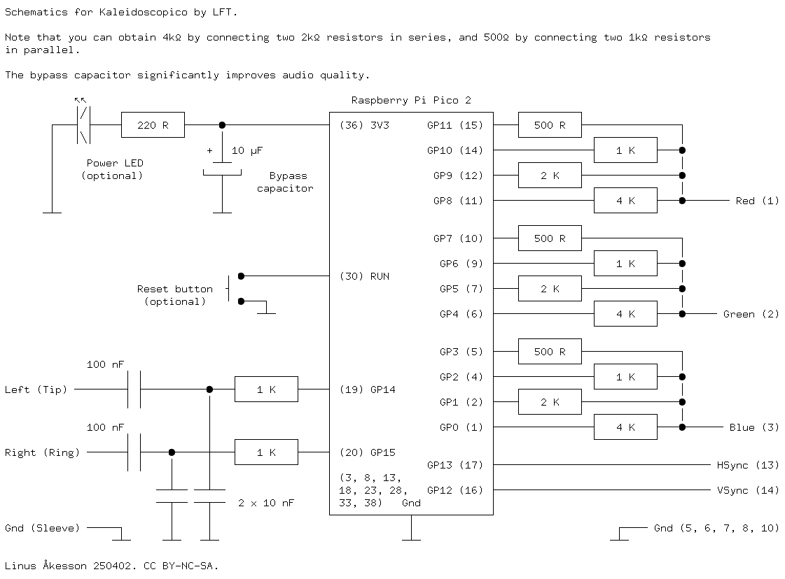
As the comment in the picture says, you can minimize the number of distinct component values by combining resistors in parallel or series. The circuit can be wired up on a breadboard quite easily. For a long time, this is what the platform looked like while I was working on the demo:
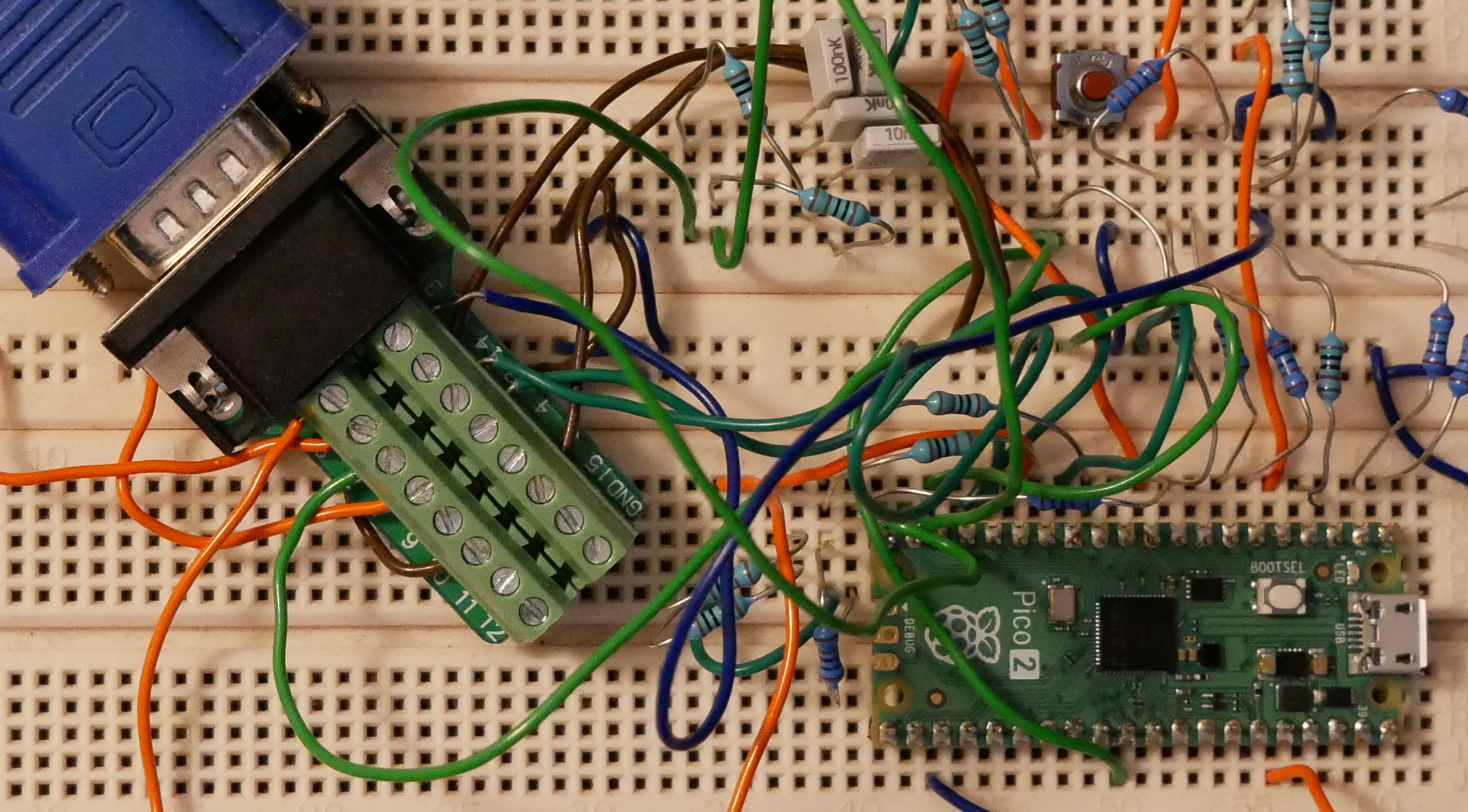
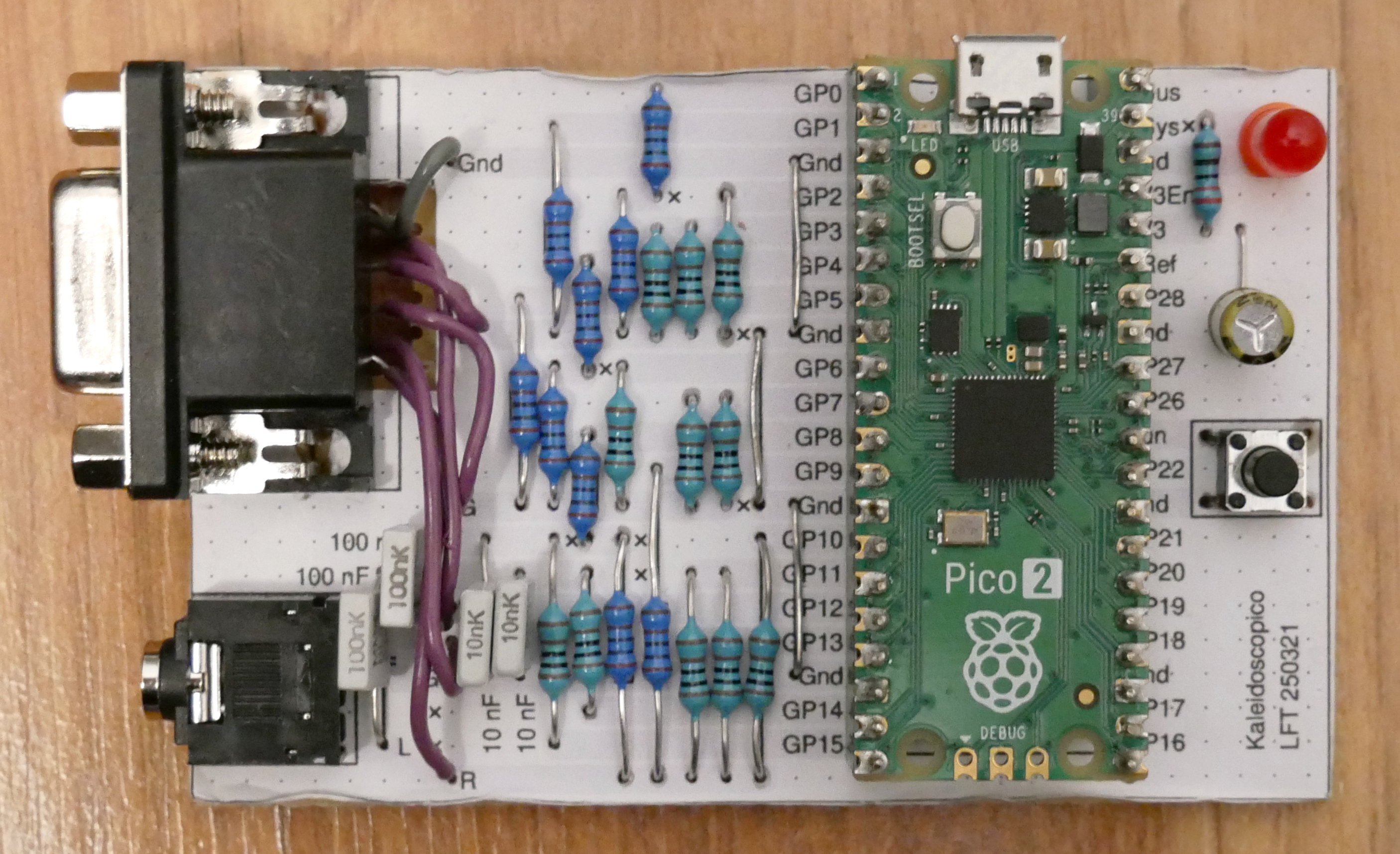
But the breadboard is electrically noisy and difficult to travel with, so I used a stripboard for the final version. You'll find the printable layout here; remember to print without scaling.
Audio is produced using pulse-width modulation (PWM), with simple RC low-pass filters to get rid of the 48 kHz carrier wave. Unfortunately the sound is very noisy because the audio signals share ground with the digital parts of the board. A good, clean power supply helps, and when I recorded the sound for the video I also disconnected the VGA cable to minimize the total load on the system.
Video generation
The CPU cores are rated up to 150 Mhz, but I'm actually downclocking to 130 MHz to better match the timing of the video signal, which is a standard 1024x768 VGA mode at 60 frames per second with a 65 MHz pixel clock. I don't use the full resolution however; the colour signals only change at half the nominal rate (i.e. one pixel every four system clock cycles), and each logical pixel row is emitted twice, so the actual resolution is 512x384 pixels.
The video signal is generated by several interlocking parts: The horizontal sync pulse is produced with PWM. One of the programmable input/output blocks (PIO) of the RP2350 is responsible for putting out the other VGA signals at the right time.
A PIO contains four programmable state machines. I use three of them to generate three separate layers of pixels. The PIO has a built-in priority mechanism that causes higher-numbered state machines to override the outputs of lower-numbered state machines, allowing the layers to have transparent pixels where lower-numbered layers shine through.
The fourth state machine is responsible for the overall timing of a scanline: it waits for the horizontal sync pulse (generated by PWM and visible as an input signal on the GPIO pad), tells the other state machines when it's time to start emitting pixels, and it also produces a solid black border outside the visible part of the screen. The border is used to implement smooth scrolling in the x-direction: The layers can start emitting pixels early, in which case the black edge covers the first few pixels.
Vertical sync is treated as a special colour, in a sense: That pin is normally configured as GPIO and driven high (the signal is active low). When the visible portion of a video frame has been emitted, one of the PIO state machines is placed in a special mode where it controls the vertical sync pin; the line is driven high at first. Then the GPIO pin is reconfigured to be under PIO control, and the state machine proceeds to generate the vertical sync pulse as though it were a regular colour output. This detour via the PIO allows the vertical sync pin to be controlled with perfect timing.
Pixels
Regular pixel data is streamed into the first three state machines using DMA. But I don't store truecolour pixels in a framebuffer, as mentioned, because it would use too much RAM. Instead, each pixel is a 4-bit value that is used as a lookup into a palette of six colours. Each layer has its own palette.
Why use four bits to represent six colours? PIO state machines are quite limited in what they can do; they are tailor-made for pushing groups of bits around with precise timing, but not much more. They can't perform arithmetic or look things up in memory. (Well, that's not entirely true: The RP2350 introduced a special instruction for doing an indexed read from a bank of four registers. But this operation overwrites a shift register that we need for incoming pixels, so we can't use it.)
People have implemented palette-based video modes on the Pico by combining PIO with DMA: A state machine takes the incoming pixel value and concatenates it with some preconfigured bits to form an address into a colour lookup-table. This address is retrieved from the PIO by a DMA channel and used to program another DMA channel that reads from the table and passes the data back to the PIO. While this is a neat hack, it results in a lot of bus traffic that is detrimental to the overall performance of the system.
I do things differently: While there are no PIO instructions for looking up a value in a table, the instruction-fetch mechanism itself is a kind of table lookup: A state machine can transfer an incoming group of bits directly to its program counter, effectively performing a computed goto. The incoming bits have to be used verbatim—there is no way to add an offset or even pad it with extra bits. Thus, with 4-bit pixel values, we can jump to one of the first sixteen instructions of the PIO program.
It would have been possible to use 3-bit pixel values instead, jumping to the first eight addresses. Those would then have to contain jump instructions to eight individual subroutines, one for each pixel value. However, it is more convenient to work with 4-bit values, because you end up with exactly two pixels per byte.
Thus, DMA is used to transfer a stream of data from RAM to each of the three state machines. Each 32-bit data word is split into eight 4-bit pixels. If we require the least significant bit of every pixel to be zero, the state machine can jump to any even-numbered address in the first half of the PIO program space, and there we can store eight small subroutines of two instructions each: One to emit a particular colour, and one to transfer the next incoming pixel to the program counter. And voilà, we have a colour lookup table!
Palette registers
But there's a snag: There is no way to squeeze an arbitrary 12-bit colour value into a PIO instruction. The instructions are 16 bits wide, and only five of those bits can be used for immediate values. Instead, we have to hold the colour values in state machine registers. And unfortunately there are only three registers we can use, called X, Y, and ISR. (The fourth register, OSR, is used for shifting in the pixels.) But the PIO mov instruction has a flag for reversing the bits of a register before transferring it to the output pins. Hence we can keep two colours in each register: One in the least significant 12 bits, and one in the most significant 12 bits in reverse bit order. We'll also configure bit 15 as the output-enable signal. When this bit is zero in a colour definition, a transparent pixel is emitted.
The beginning of the PIO program looks like this:
00:   mov pins, null
01:   out pc, 4         [2]
02:   jmp 01
03:   out pc, 12
04:   mov pins, isr
05:   out pc, 4         [2]
06:   mov pins, ::isr
07:   out pc, 4         [2]
08:   mov pins, y
09:   out pc, 4         [2]
0a:   mov pins, ::y
0b:   out pc, 4         [2]
0c:   mov pins, x
0d:   out pc, 4         [2]
0e:   mov pins, ::x
0f:   out pc, 4         [2]
Start at any of the out pc, 4 instructions: Fetch four bits and transfer them to the program counter, effectively jumping to address 0, 2, 4, 6, 8, a, c, or e (the syntax [2] means to insert an extra delay of two cycles). Values in the range 4..e cause a colour value to be emitted from one of the registers (possibly bit-reversed as indicated by the :: prefix). The value 0 emits a transparent pixel (using the special null register that is always zero, and therefore doesn't activate the output-enable signal). The value 2 does not change the output pins; this can be used to stretch (repeat) the last pixel horizontally.
Now, because this “repeat last pixel” command can be implemented with just one instruction (a jump), this leaves a free instruction slot at address 03. Here we put a backdoor, namely an instruction to read 12 additional bits and jump to that address. This lets us extend the PIO program with more functionality, such as loading new colour values into the registers or waiting for the next horizontal sync signal. PIO programs can't contain more than 32 instructions in total, so five bits would have been enough to encode an arbitrary jump target, but we pad to twelve bits to keep things aligned neatly in the pixel stream.
So in addition to six user-configurable colours (4, 6, 8, a, c, e), there is transparency (0), repeat-last (2), and the special pixel value 3 that triggers a jump to an arbitrary address in the PIO program. As you can probably guess, a stray 3 in the framebuffer can trigger all sorts of interesting bugs. During development, I would initialize all unused RAM to 0x33333333 so I could notice right away if a state machine picked up something it wasn't supposed to.
Coppers
As mentioned, one of the CPU cores—Core 1—spends all of its time in a tight loop with one iteration per scanline. This loop starts with a busy-wait on the horizontal sync signal (which you'll recall is generated by PWM). Then—and this task has to complete during the horizontal blanking period—it parses a copperlist, a series of simple instructions in memory. In this system there are only two copper instructions: Wait for a particular rasterline, and store a constant value in one of the “chipset registers” (global variables). The registers control everything from state-machine palette values to framebuffer pointers and horizontal scroll offsets, but they are of course just regular data words stored in memory. Subsequent code in the Core 1 loop will pick them up and react accordingly.
Notably, this software-defined chipset has not one, but two independent coppers. This is very useful for layered effects. For instance, one layer might display a scrolling tiled background image, with one of the copperlists being responsible for the seams where framebuffer pointers have to be reset back to the beginning of the tile. Meanwhile, another layer could display an entirely different copper-intensive effect such as a bitmap stretcher, where the parameters of the wait instructions fluctuate as part of the animation. In a single-copper system, the copperlists for the two layers would have to be merged, for each video frame, into a single list. Since my chipset is implemented in software, it's much easier to just perform the merging dynamically while the frame is produced, by maintaining two copper pointers.
Here's a commented version of the inner loop for one of the coppers. Register s11 points to the next instruction in the copperlist, and register s10 holds the number of the current rasterline:
        j       loop            # jump to loop entry-point
store:
        add     a0, a0, gp      # compute target address
        sh      a1, 0(a0)       # and update the register
loop:
        lh      a0, 0(s11)      # read register offset, or 0 for wait
        lh      a1, 2(s11)      # read parameter
        addi    s11, s11, 4     # increment pointer to next instruction
        bnez    a0, store       # branch if this was a store instruction

        bgeu    s10, a1, loop   # keep looping if we've reached the line

        addi    s11, s11, -4    # otherwise done for now; undo last increment
Framebuffer DMA
When both coppers have reached a waiting state, Core 1 proceeds to set up the PIO state machines and DMA for the upcoming line. Three DMA channels are configured to feed one line's worth of pixels into each of the pixel-emitting PIO state machines. A line is 512 pixels across, corresponding to 64 words. But because of the smooth-scrolling feature, the line might be shifted anywhere from zero to seven pixels to the left. Therefore, the DMA channels are configured to transfer 65 words per line, and for non-scrolling parts this extra word turned out to be a popular place for stray uninitialized pixels to sneak in and hang the state machines.
An interesting gotcha: The RP2350 DMA block keeps track of how full the PIO FIFO is, and holds off until there's room for more pixels. But it does this using an internal counter rather than looking at the actual state of the FIFO. I'm sending commands (i.e. the special pixel value 3 followed by a PIO address) directly from the CPU when preparing for a new line, but then I transmit the actual pixels using DMA. Hence I must ensure that the FIFO is completely empty before switching between the two methods, otherwise some data could be lost.
Ring buffers and tiling
The DMA controller has a ring buffer mode in which a channel can keep its read or write address within a naturally aligned block of memory, effectively wrapping the lower bits while keeping the upper bits constant. The datasheet suggests that this can be used for streaming applications, where for instance the software constantly renders new data into a circular buffer and the DMA consumes it, but I also found it very useful for graphical effects.

A ring buffer that is smaller than the width of the screen results in a repeating pattern of pixels across the rasterline, i.e. horizontal tiling. This can be seen in the kaleidoscope backgrounds, which are only 256 pixels wide; two copies are displayed next to each other.
Conversely, a ring buffer that spans an entire rasterline (or more) behaves like a wide, cyclical canvas that can be positioned anywhere relative to the viewport. Together with the smooth-scrolling feature, this allows you to scroll graphics or text horizontally across the screen without having to worry about the seam at the wraparound point.

For instance, the city skyline in this screenshot is a static bitmap displayed by the bottom layer. It's exactly as wide as the screen: If you look closely while the effect is running, you can see that the buildings that disappear at the left edge of the screen reappear at the right edge. If the scrolling had kept going, you would eventually have seen the moon in two places, breaking the illusion.
But let's return to what Core 1 is doing on each scanline, after it has finished setting up the DMA transfers.
Sound synthesis
The VGA mode I use has a line frequency of 48.363 kHz, which is also a reasonable audio sample rate. A stereo line-out signal is produced using a pair of PWM channels that are synchronized with the video generation. There are 2688 cycles per rasterline, so this is used as the PWM period, and the channels are initially started somewhere during the horizontal blanking phase. This means that we can compute a new stereo sample on each rasterline and hand it over to the PWM block at any time during the visible part of the line, and the values will be picked up when the counters wrap around during blanking. It also means that we only have a range of 2688 voltage levels at our disposal, corresponding to sligthly over 11 bits of audio resolution. This seems low, but sounds good in practice. The noise floor from the power rail is higher.
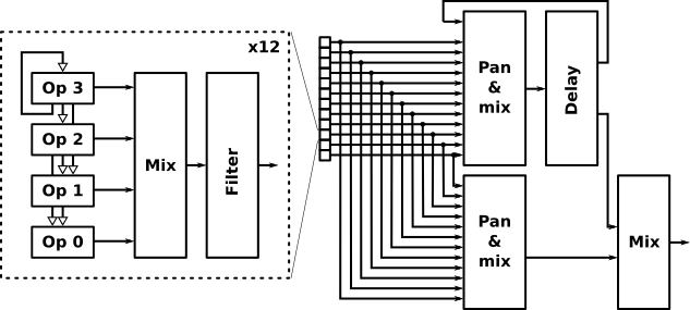
Thus, as soon as the pixel DMA is up and running for all three layers, Core 1 goes on to compute the next stereo sound sample. I've implemented a 12-channel phase-modulation synthesizer. Each channel comprises four operators and a resonant filter, and the mono outputs from the twelve filters are panned and mixed to produce two separate stereo outputs: a main signal, and an input to a global delay (echo) effect. The output from the delay is attenuated and fed back into the delay input, and also combined with the main signal to produce the final output.
The audio computations are carried out with 16 bits of precision (using 16.16 fixpoint math), so for the final output the lower five bits have to be truncated. I save those bits and add them to the next generated sample before truncating that, and so on. In this way, rounding errors cancel out over time through dithering. But as I said, the noise floor is so high that this probably doesn't make an audible difference.
The twelve channels are handled in a loop, but within each channel the four operators are implemented in an unrolled fashion because they are slightly different in terms of where their modulation input is coming from.
Here's commented code for operator 0, which is modulated by operators 1 and 2. Register a5 points to a structure containing parameters for the current channel, and s7 points to a sine table consisting of 512 halfwords.
        lw      a1, FMC_FREQ0(a5)       # get frequency of operator 0
        lw      a4, FMC_PHASE0(a5)      # get current phase of operator 0
        lhu     t1, FMC_MOD0BY1(a5)     # get modulation amount (8.8 fixpoint)
        lhu     t2, FMC_MOD0BY2(a5)     # get modulation amount (8.8 fixpoint)
        add     a4, a4, a1              # advance the phase...
        sw      a4, FMC_PHASE0(a5)      # ...and store it
        srli    a4, a4, 8               # shift right by 8 to adjust range
        lh      a1, FMC_OUTPUT1(a5)     # get the modulation input values...
        lh      a2, FMC_OUTPUT2(a5)
        mul     t1, t1, a1              # ...multiply by the desired amount...
        mul     t2, t2, a2
        add     a4, a4, t1              # ...and add to the phase
        add     a4, a4, t2
        srli    a4, a4, 15              # now put the phase in the low 9 bits
        andi    a4, a4, 511             # and mask away any higher bits
        sh1add  a4, a4, s7              # compute address (a4 = a4 << 1 + s7)
        lh      a0, 0(a4)               # read a value from the sine table
        sh      a0, FMC_OUTPUT0(a5)     # store as the output from this operator
Tracker and playroutine
The parameters for the synthesizer, such as FMC_FREQ0 and FMC_MOD0BY1 above, are updated by a playroutine that executes once per video frame during vertical blanking. The playroutine is parsing music data stored in flash.
I composed the music in a custom-made tracker, thrown together for the project. Since I had no plans to reuse it, the user interface is raw and minimal:
At the top is an instrument editor, with fixed-function parameters to the left and four general-purpose programs to the right. Further down and to the right is the song structure editor with twelve channels. These numbers decide what “track” goes where in the song; a track is a single-channel block of note data, 32 steps long. Down and to the left is the editor for the track data, which is a view into the current song line.
The structure with reusable tracks that can appear in multiple parts of the song is only there to facilitate the composing process. The finished song is rendered out into a set of twelve run-length-encoded streams, one for each channel. The streams contain note events and commands to update the synth parameters; they also make references to the instrument data which is stored in a separate table.
The playroutine executes on Core 0, which leads us naturally to the next subject.
Demo framework
If Core 1 is the chipset, Core 0 takes the traditional role of a CPU in a demo-making context, which is to render and orchestrate the effects themselves.
System memory
The RP2350 is equipped with 520 kB of RAM organized in different banks that are hooked up to the system bus fabric in different ways. Specifically, there are two 4 kB areas with dedicated bus ports. This means that a core (or the DMA subsystem) can read or write to one of these memory areas at the same time as other memory is accessed by some other part of the system. I'm executing the Core 1 codebase—the realtime chipset implementation—from one of these banks to ensure that it doesn't stall on instruction fetches.
The other 4 kB bank contains some performance-critical resident code for Core 0. Most of the time, however, Core 0 is running code from the execute-in-place (XIP) area, which is a cached view into the 4 MB flash memory of the Pico 2. Both of the special 4 kB banks also contain global variables, including chipset “registers” and synth parameters. I've set the RISC-V global pointer register (gp) to the address at the boundary between the two banks, such that global variables in both are reachable at positive and negative offsets.
A series of parts
When a new vertical blanking period starts, Core 1 sends a so called doorbell interrupt to Core 0. The interrupt handler is one of the aforementioned routines that execute from RAM, and it is responsible for invoking the music playroutine and then jumping through a callback vector to some code that is specific to the current demo part.
In addition to the vertical-blanking interrupt handler, Core 0 also has a main thread that invokes other callback routines related to the current part, while also monitoring the current song position to determine when it's time to move on to the next part.
A demo part has a total of four callbacks: The normal interrupt routine, the fade-out interrupt routine, and two routines that are called in main context: prepare (called once) and main (called repeatedly).
The role of the main thread on Core 0 is illustrated by the following diagram:
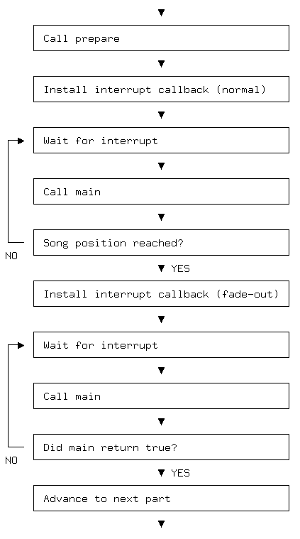
Note in particular that the fade-out interrupt routine of one demo part remains installed while the prepare routine of the next part is called.
Memory areas for the effects
The bulk of the system RAM, the 512 kB that doesn't have dedicated bus ports, is freely available for use by effect code. And the effects just write directly to hardcoded addresses defined with labels at the top of their source code files, like this:
BIGBALLOON_FB   = 0x20020000    # 384 rows of 256 bytes, 0x18000
FIREANIM        = 0x20038000    # 32 frames of 32 rows of 24 bytes, 0x6000
SKYLINE_FB      = 0x20040000    # 384 rows of 256 bytes, 0x18000
I don't use the Pico SDK (Software Development Kit) and my code has only .text sections (flash content), so there's no need to worry about overwriting somebody else's data in memory, as there's no such thing. However, the parts must take care not to overwrite each other's memory. To help keep this straight, I divided the memory into sub-areas as follows:
20000000-2001ffff       Area 1 (128 kB)
20020000-2003ffff       Area 2 (128 kB)
20040000-2005ffff       Area 3 (128 kB)
20060000-20061fff       Global sine table (8 kB)
20062000-20062fff       Spare Area A (4 kB)
20063000-20063fff       Spare Area B (4 kB)
20064000-20069f5f       Core 0 stack (largely unused)
20069f60-2007ffff       Echo buffer (88.15625 kB)
The peculiar size of the echo buffer comes from the duration of one musical beat, which happens to be 28 video frames times 806 rasterlines (samples). Yes, the tempo of the music determines the initial system stack pointer. Why not?
A demo part may use any combination of Areas 1, 2, 3, A, and B, as long as they're not in use by the parts immediately before and after it. An exception is that a part may inherit the contents of a data area from its predecessor.
I implemented each major demo effect as a standalone part first, with a prepare routine that would set up all the necessary data, either programmatically or by copying or decrunching it from flash memory. Then I gradually introduced intermediate parts that would transition between the effects and weave them together, and these would often inherit assets.
The callback routines for the various parts are listed in one big table, along with the song positions that trigger the transitions. Here's an extract:
   .word  prejelly1_prepare,      prejelly1_vbl,      prejelly1_vbl,         prejelly1_main,      0        # ---A
   .word  prejelly2_prepare,      prejelly2_vbl,      prejelly2_vbl,         prejelly2_main,      0        # --3|
   .word  jellycube_prepare,      jellycube_vbl,      jellycube_vblout,      jellycube_main,      105*112  # 12|-
   .word  tweenjelly_prepare,     tweenjelly_vbl,     tweenjelly_vbl,        tweenjelly_main,     0        # --|A
   .word  animjellycube_prepare,  animjellycube_vbl,  animjellycube_vblout,  animjellycube_main,  112*112  # 12|-
   .word  postjelly_prepare,      postjelly_vbl,      postjelly_vbl,         postjelly_main,      0        # --|A
The columns are: Prepare, normal vertical blanking, fade-out vertical blanking, main, transition condition. As you can see, the two vertical-blanking routines are often the same.
Also note the comments that document which memory areas are used. The pipe character means that the contents of the area are inherited from the previous part.
Transitions
A non-zero transition condition indicates a song position in frames; 112 frames correspond to one bar of music. The framework proceeds to the fade-out stage if the current song position is greater than or equal to the given number. Consequently, if the condition is zero then a transition is triggered as soon as possible.
In practice “as soon as possible” is when the prepare routine of the current part has finished and the main routine has returned once. But the main routine can use its return value to prolong a part until a transition or fade-out has completed.
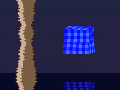
In the extract above, Area 3 contains data for the vertical audio visualizer that is present on the left-hand side of the screen when the blue jellycube is visible, and on the right-hand side when the black and white animjellycube is shown. There is no need (or time) to recompute the data for the audio visualizer between the parts, so it is inherited. Meanwhile, animjellycube needs to prepare new data in Areas 1 and 2 in order to do its thing, so it cannot follow jellycube directly. This calls for an intermediate part (tweenjelly) with a small memory footprint. That part draws only the visualizer—using inherited data in Area 3 and a small copperlist in Area A—and moves it smoothly across the screen from left to right.
Similarly, prejelly2 makes the visualizer appear smoothly from the left, and postjelly makes it disappear smoothly to the right. The reason for having two separate prejelly parts is that just before this excerpt, there was a part that used all three big areas (1–3). It would not be possible to prepare new data in Area 3 while the interrupt handler of that part was still active. Thus, prejelly1 briefly displays a plain blue background with a horizon while the prepare routine of prejelly2 is called.
We'll now proceed to take a look inside two of the major demo parts. The first is the greetings part, which is a simple copperlist effect on top of a rotozoomer. The second is the final balloon ride over a 3D landscape.
The greetings part

The greetings part consists of two layers, each controlled by a separate copper. The bottom layer (Layer 0) is a so called rotozoomer and the top layer (Layer 2) contains the header logo (the word “greetings”) and up to eleven rows of text. Layer 1 is actually used briefly while the part is fading in, but we won't go into that here.
The prepare routine of the greetings part starts by decrunching the header logo into RAM at the address HEADERFB_ORG (FB is short for framebuffer, and ORG means the origin of the buffer).
        la      a0, _binary_greetings_headerlogo_pak_start
        la      a1, HEADERFB_ORG
        call    decrunch
Like most assets in the demo, the logo is compressed in flash with a simple Lempel-Ziv compression tool that I made for the project. In this case, the unpacked logo is 24 kB whereas the size on flash is only 1264 bytes. So as you can imagine, compression has a huge impact on the overall size of the demo.
Anatomy of a copperlist
Next, a copperlist is prepared at another address. The beginning of the copperlist is copied from a template in flash:
coppersrc:
        .hword  COP_WAIT,       0
        .hword  COP_L2|L_ADDRH, HEADERFB_ORG>>16
        .hword  COP_L2|L_ADDRL, HEADERFB_ORG&0xffff
        .hword  COP_L2|L_MODE,  MODE_RING512
        .hword  COP_L2|L_XSCR,  0
        .hword  COP_L2|L_PITCH, 256
        .hword  COP_L2|L_COL1,  0x111
        .hword  COP_L2|L_COL2,  0x5c5
        .hword  COP_L2|L_COL3,  0xfff

        .hword  COP_WAIT,       96*2
        .hword  COP_L2|L_MODE,  MODE_OFF
        .hword  COP_L2|L_COL1,  0xfff
        .hword  COP_L2|L_PITCH, 512
coppersrc_end:
The first halfword in a pair is the target “register” (offset from the global pointer), except when it is zero (COP_WAIT). We don't actually need to wait for line zero at the beginning; that's only a placeholder. This value is going to be updated later, along with the 96*2 further down, in order to move the header logo up and down on the screen.
The logo is 96 pixels tall, so note that the parameter to COP_WAIT is the physical line number (as in the 1024x768 VGA mode). This is just an early design decision that stuck around vestigially: The entire demo runs at half resolution, doubling each line, but it's technically possible to wait for the in-between lines as well.
COP_L2 is an offset to a group of chipset registers related to Layer 2. The various parameters work as follows: ADDRH and ADDRL determine the high and low halfword of the current framebuffer address. The PITCH is automatically added to this address after every pair of physical rasterlines. XSCR controls the smooth-scrolling offset from 0 to 7, and COL1..6 determine the palette. For the header logo we only need three colours: near-black, green, and white.
MODE determines how Core 1 will set up the DMA for this and subsequent lines. In this case, RING512 selects a ring-buffer that is 512 pixels wide. We're not going to scroll the logo sideways, so in this case it's not obvious why we need the tiling properties of a ring buffer. It's there to force the 65th data word (which is hidden by the right-hand side border) to be fetched from somewhere inside the framebuffer. Otherwise this word might contain uninitialized data that hangs the state machine.
The prepare routine now proceeds to generate eleven chunks of copperlist data, corresponding to the eleven rows of text that will follow. The first chunk ends up looking like this:
        .hword  COP_WAIT,       140*2
        .hword  COP_L2|L_XSCR,  0
        .hword  COP_L2|L_ADDRH, ROWFB_ORG>>16
        .hword  COP_L2|L_ADDRL, ROWFB_ORG&0xffff
        .hword  COP_L2|L_MODE,  MODE_RING1024

        .hword  COP_WAIT,       156*2
        .hword  COP_L2|L_MODE,  MODE_OFF
As you can see, the text will be displayed using a 1024x16 framebuffer at ROWFB_ORG. In fact eleven such buffers are laid out consecutively in memory, so the second chunk is going to set the address to ROWFB_ORG + 16*512 and so on. Recall that pixels are 4-bit values, so 1024 pixels occupy 512 bytes of memory.
The very last instruction in the copperlist, and in every other copperlist in the demo, looks like this:
.hword COP_WAIT, 0xfff
It's all right to wait for a line number that never occurs. After the last visible rasterline, the code running on Core 1 simply refrains from executing copper instructions and resets the copper pointer from a global variable. That variable is set from the vertical-blanking routine of the effect, like so:
greetings_vbl:
        la      a4, COP_ORG
        sw      a4, G_COPPERLIST1(gp)
The greetings_vbl routine proceeds to compute new values for some of the fields in the copperlist. This includes the vertical position of the header, the start address of the header (in case the header is positioned partially above the screen), the smooth-scrolling positions of the text rows, and the start addresses (course scrolling positions) of the text rows.
The main routine (greetings_main) is responsible for drawing characters into the off-screen parts of the text-row buffers. It does this by copying character graphics from a font stored in flash and accessed through the XIP cache.
The rotozoomer
Now we turn to the rotozoomer in Layer 0. From a copperlist perspective, this is just a static full-screen framebuffer (512x384 pixels, 96 kB), the contents of which will be updated by the main routine.
A texture, 128x128 pixels in size, has been prepared in memory at TEX_ORG. You may have noticed that the background is a checkered pattern with a much lower resolution than this, but that was an aesthetical choice made later; the code supports 128x128. These pixels are stored as individual bytes rather than packed 4-bit values.
The vertical-blanking routine decides how this texture should be mapped onto the screen during the upcoming frame. The desired position, orientation, and size are communicated—via a set of variables in memory—to the main routine which is responsible for filling the framebuffer with pixels from the texture. But filling an entire framebuffer calls for a highly optimized pixel-copying loop, and this is where the RP2350 interpolator enters the picture.

The interpolator offers a number of quirky modes and options, and here I'll only describe its affine transformation capability. This is a tool for stepping through a two-dimensional array using fixpoint coordinates. It's more or less exactly what a rotozoomer does—but the functionality is put to good use elsewhere in the demo too.
In this mode, the interpolator works as follows: We set up values in the two accumulator registers and the three (somewhat strangely named) base registers. Every time we read from a special register in the interpolator, we obtain an address constructed from the upper bits of Base 2 and the two accumulators. These bits correspond to the base address of the texture, the row, and the column, respectively. Furthermore (triggered by the same read) base registers 0 and 1 are added to their respective accumulators.
The following loop steps through the pixels of a single rasterline. Note that while the texture uses one byte per pixel, we still have to pack two pixels per byte for the framebuffer:
loop:
        lw      a0, 0x9c(s9)    # INTERP0_POP_FULL
        lw      a1, 0x9c(s9)    # INTERP0_POP_FULL
        lbu     t2, 0(a0)       # read from the texture
        lbu     t0, 0(a1)       # read from the texture
        addi    a5, a5, 1       # advance destination pointer
        slli    t0, t0, 4       # shift the second pixel
        or      a0, t2, t0      # combine them
        sb      a0, -1(a5)      # and store in the framebuffer
        bltu    a5, a6, loop    # loop until end of line
On RISC-V, after you load a value from memory you have to wait one cycle before using it (in the general case), otherwise an extra wait-cycle will be inserted. Thus, by incrementing the destination address (a5) before using it, a wait-cycle in the data-path of t0 is avoided.
Of course, this inner loop is part of an outer loop that iterates over all the rasterlines. The outer loop needs to prepare new values in the interpolator accumulators for each line, so it keeps track of the texture coordinates of the first pixel of the current line, and how much to add to these coordinates as we proceed down the left edge of the screen.
The landscape part

When the balloon is soaring over the landscape towards the end of the demo, all three layers are in use, as well as both coppers and all three big memory areas.
The top layer, along with one of the coppers, is responsible for displaying the “zoomballoon” as it's called in the code. The hot air balloon is rendered in a number of different ways throughout the demo, and the zoomballoon version allows the size to be changed smoothly.
The following texture reveals how it is done:

The balloon is formed by picking out individual lines from the texture and piecing them together on the screen using a copperlist. Since the framebuffer pointer has to be updated on every rasterline, the copperlist is quite long (384 * 3 = 1152 instructions). To allow the balloon to be positioned partially outside the viewport (not used here, but in other parts of the demo), each line of the texture is 1024 pixels wide and mostly blank. Together the texture and copperlist fit nicely inside memory Area 3.
The other copper is responsible for the landscape, which is rendered in seven colours using a static full-screen framebuffer. The framebuffer is displayed as Layer 1. Its palette provides six of the colours, and the final colour comes from Layer 0 (it appears when the transparent pixel value is used in the framebuffer).
Layer 0 runs in a special mode, MODE_SOLID1, where it constantly emits the first colour of its palette. The chipset code doesn't trigger any pixel DMA transfer for this mode.
Since we are going to compute these pixels in realtime, it seems a bit awkward that the seven colour values—0, 4, 6, 8, a, c, e—aren't consecutive. But they are arranged in a gradient from dark green to light blue in the following order: 4, 6, 8, a, c, e, 0. This makes them consecutive modulo 16.
The shape of the mountain landscape is precomputed and stored as a height map, 256x256 bytes in size, tiling seamlessly in both directions. The map occupies memory Area 2, leaving Area 1 for the full-screen framebuffer.
The landscape is rendered column-wise, from left to right, but memory is tight and we can't afford double-buffering for this effect. This inevitably leads to tearing. But we're flying over the landscape at a stately pace and there's not much going on in the upper part of the screen anyway, so the tearing is not really noticeable.
I won't go into the details of how to render a mountain landscape, but in short: For each column, we cast a ray into the height map, from the eye towards the horizon. We compute pixels from the bottom up, while stepping along the ray using fixpoint coordinates. Now, stepping through a tiling 2D map using fixpoint coordinates—doesn't that sound familiar? That's right, I'm using the interpolator here too.
Random dithering
The raycasting routine runs at half the horizontal resolution, so each frame is constructed from 256 columns. In addition to being roughly twice as fast as working at full resolution, this simplifies the framebuffer addressing: Each double-width pixel occupies one byte of memory. We could either store the same pixel value in both nibbles (e.g. 0x66 for a double-width pixel of colour 6), or use the special pixel value 2 to repeat the last colour (0x26—the packed pixels are stored low-nibble-first since we're on a little-endian system).
But we can do better! The pixels coming out of the raymarcher are 8-bit brightness values, and we can map them onto the seven colours with dithering to create an illusion of greater colour depth. And we can even produce an impression of full horizontal resolution by dithering the same brightness value twice to obtain separate colour values for the nibbles. A straightforward way of doing that is to use random dithering: Suppose we start with a brightness value in the range 0x40..0xff. We add a random number in the range 0x00..0x1f, and then we mask away the five lower bits. The masking truncates the value to obtain a discrete palette index, but by adding a random number first, relatively bright pixel values are more likely to be rounded up instead of down.
If we also treat the result as an unsigned byte, its value is either 0x40, 0x60, 0x80, 0xa0, 0xc0, 0xe0, or 0x00, which fits our gradient palette perfectly. We do the same thing again (with a different random number), and shift it down to the low nibble, before combining the two values and storing the result in the framebuffer.
This dithering technique calls for a large amount of pseudo-random numbers. We could calculate those numbers on the CPU by implementing a linear-feedback shift register, but I discovered a faster way that is also more fun: The DMA controller on the RP2350 has the ability to calculate a checksum of the transferred data. This checksum is available in a register that is updated continuously while the transfer is in progress. If we configure a DMA channel to repeatedly read its own checksum register and send the result to a PIO state machine, we will obtain a stream of pseudo-random checksums. The PIO state machine then splits the 32-bit data words into smaller chunks and makes them available to the CPU via its output FIFO.
It would be possible to read pseudo-random words directly from the DMA register using the CPU, but then there would be no natural way to pace the DMA channel. It would either have to run at full speed (saturating the bus) or at some arbitrary rate determined by a timer. The PIO provides demand-driven flow control, because the DMA channel can be configured to hold off when the incoming PIO FIFO is full.
On the CPU side, there is no need to check whether a new value is available from the PIO or not, because the pseudo-random generation is so fast. It's really just a matter of reading the FIFO register to get an infinite supply of pseudo-random numbers for free.
Final words
I had a lot of fun making this demo, and learned a lot as well. The RP2350 turned out to be a charming chip in many ways, the RISC-V instruction set was surprisingly fun to work with, and the Pico 2 makes it all very accessible. I recommend that you give it a try!
Posted Friday 25-Apr-2025 08:34
Discuss this page
Disclaimer: I am not responsible for what people (other than myself) write in the forums. Please report any abuse, such as insults, slander, spam and illegal material, and I will take appropriate actions. Don't feed the trolls.
Jag tar inget ansvar för det som skrivs i forumet, förutom mina egna inlägg. Vänligen rapportera alla inlägg som bryter mot reglerna, så ska jag se vad jag kan göra. Som regelbrott räknas till exempel förolämpningar, förtal, spam och olagligt material. Mata inte trålarna.
Ferdinand Bachmann
Fri 25-Apr-2025 10:29
The idea of using bit reversal and PIO code addresses as a color lookup table is *genious*! That seems much more flexible and allows for nice paletted framebuffers that don't explode the RAM while still giving you lots of freedom. There a so many different mode ideas, but this one just seems really useful for demo effects. Back when I made my demo, I experimented with run-length encoded full-color modes (used in my demo pico4k) or 1-bpp black and white modes (hello bad apple, done via decrementing black to get white), but couldn't figure out how to do a palette.
I also found it interesting how you did vsync and hsync via gpio role switching and PWM, that must have been tricky to time right, but is probably better than the dedicated interrupt and PIO fifo for line timings I had in my demo. That one ate too many cycles at unpredictable points in time.
Simulating a copper-like thing on the second core is also really nice, since it probably makes writing the effects more similar to oldskool platforms.
I'll definitely try and see what I tricks I can build with the extra ideas from this one whenever I make another pico thing.
Thanks!
PS: have you tried how fast you can overclock the RP2350? The RP2040 can go as high as 420MHz in my testing without getting warm, and as far as I see, the PIO, GPIO, and PWM can keep up, but the flash needs to be clock-divided or left unused. Could potentially be fun for some mind-bogglingly complex effects that would be too cpu-intensive for the pico otherwise.
8 more comments hidden. Click to show all.
Sun 20-Jul-2025 22:05
Any chance that you'll release the source code to the demo one of these days? I'm pretty sure I'm not the only one who would like to learn from you in that way!
Mon 11-Aug-2025 17:15
The pinout is not that much different from yours.
Sun 21-Sep-2025 00:58
Mon 16-Feb-2026 21:15