


The Family Bass
I connected a Family BASIC keyboard to an NES via a bespoke adapter in order to play its unique triangle waveform live.
Here's a short technical presentation:
And here's a performance of my NES-style tune Platform Hopping, originally composed for the music compo at X 2023:
Download
- Linus Akesson - Platform Hopping (Family Bass).mp3 (MP3, 5.7 MB)
How the adapter works
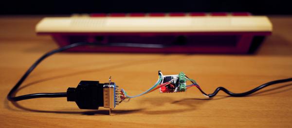
As outlined in the presentation video above, the Family BASIC keyboard is designed to plug into the expansion port of the Famicom, but I wanted to hook it up to one of the controller ports on my NES. This called for a custom adapter.
The keyboard

The 72 keys of the Family BASIC keyboard are wired up in a simple matrix, nine rows by eight columns, and the columns are further subdivided into half-columns of four bits each. During transmission, there's also a tenth row that is left blank. This is because the protocol is designed around a 4017 decade-counter chip inside the keyboard, which is responsible for driving one row of keys at a time. An input signal to the keyboard selects between the two half-columns of the current row, and the same input signal also acts as a positive-edge clock to the decade counter, advancing to the next row. After ten positive edges, the cycle repeats. There's also a separate reset input. In summary:
| Direction | Function |
|---|---|
| To keyboard | Reset |
| To keyboard | Half-row select and Clock |
| From keyboard | Data 1 |
| From keyboard | Data 2 |
| From keyboard | Data 3 |
| From keyboard | Data 4 |
(I'm ignoring a few additional signals that control two jacks at the back of the keyboard, used for storing BASIC programs to tape and loading them back.)
The NES controller ports
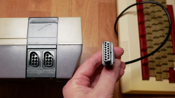
Now let's turn to the NES controller ports. Here we find two output signals called OUT and CLK and three input signals. OUT is actually a common signal shared by both ports, while CLK and the input pins are available for each port separately.
However, the cable I'm plugging into the oddly-shaped NES port happens to be a replacement cable for a standard controller, and the standard controllers only make use of one of the input pins. To save cost and make the cable as flexible as possible, only the signals that are actually used by the controller are connected. Thus, the only signals I can use are:
| Direction | Function |
|---|---|
| From NES | OUT |
| From NES | CLK |
| To NES | Data |
OUT and Data are easy to access from software running on the NES, by writing and reading a hardware register respectively. But the CLK signal is different: It generates a pulse every time the corresponding Data register is read.
Inside each hand controller, a parallel-in, serial-out shift register chip is connected to these three lines, so that the NES can assert OUT to latch the status of all eight buttons into the shift register, and then read Data eight times to clock it out, one bit at a time. Such automatic CLK generation is handy when interfacing standard controllers, but it's a bad fit for the protocol used by the keyboard, so we can't really make use of this signal.
That leaves us with a single output line and a single input line.
The serial protocol
I wired OUT straight to the “Half-row select and Clock” line, which allows me to cycle through the keyboard matrix one half-row at a time. There was no room for the Reset signal, but I solved that in the user interface, as explained in the video.
That still leaves us with four data signals coming from the keyboard, and only a single input on the NES side. I decided to use an AVR ATtiny85 microcontroller to multiplex the four parallel signals into a UART-like bitstream. This chip has five GPIO pins, which is exactly what we need.
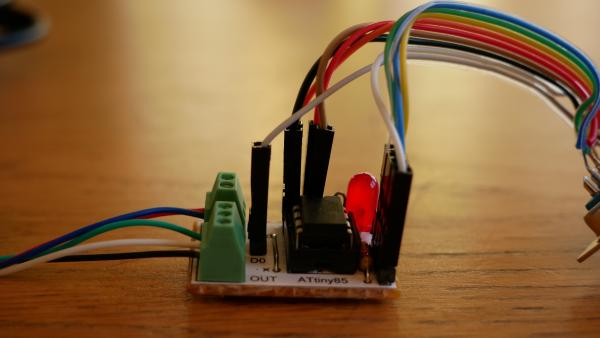
Of course, a bigger microcontroller would have allowed a more sophisticated protocol and state-machine, probably also incorporating the Reset signal to the keyboard. But I like the compact DIL8 package.
The serial output works like this: First, the signal is idle (high) for a period of at least five bit-times. This is followed by a start-bit (low) and four data bits, and then the signal returns to idle. That way, the receiver can wait for a sufficiently long continuous high level—guaranteed to be the idle state—and sync up with the next transition to a low level (i.e. the start bit) to know when the data bits are due.
The ATtiny85 is clocked by its internal calibrated RC oscillator and runs at about 1 MHz. The code is implemented in assembly language, arranged to make each data bit exactly six cycles long, which comes out to 6 μs.
Turning now to the receiving end, a PAL NES is running at 1.66 MHz. We first wait for a sufficiently long stretch of high level (the bit in the register is inverted):
        lda     #$01

waitforidle
        bit     $4017
        bne     waitforidle

        bit     $4017
        bne     waitforidle

        bit     $4017
        bne     waitforidle

        bit     $4017
        bne     waitforidle

        bit     $4017
        bne     waitforidle

        bit     $4017
        bne     waitforidle

        bit     $4017
        bne     waitforidle
Then we immediately busy-wait for a low level:
waitforstart
        bit     $4017
        beq     waitforstart
This loop takes seven cycles per iteration, and the signal could toggle at any time during the loop, so we now have to a jitter of up to 6 / 1.66 MHz = 3.6 μs. That is well within a bit-time; the extra margin is good to have because of the imprecise RC oscillator.
Then we simply read the data bits, exactly ten NES-cycles (6.0 μs) apart:
        nop		; wait 2 cycles
        bit     0	; wait 3 cycles

        lda     $4017
        nop
        sta     temp1
        lda     $4017
        nop
        sta     temp2
        lda     $4017
        sta     temp3
        lda     #$01
        and     $4017
...and put the bits together:
	lsr     temp3
        rol
        lsr     temp2
        rol
        lsr     temp1
        rol
In the above, I've left out a bit of protective code to deal with the situation where an interrupt occurs during our timed code. This is just a matter of setting a flag at the beginning of the critical section, clearing it in the interrupt handler, and checking that it's still set at the end of the critical section. If any such interference was detected, we have to wait for the next idle period and try again.
Posted Friday 17-Jan-2025 07:59
Discuss this page
Disclaimer: I am not responsible for what people (other than myself) write in the forums. Please report any abuse, such as insults, slander, spam and illegal material, and I will take appropriate actions. Don't feed the trolls.
Jag tar inget ansvar för det som skrivs i forumet, förutom mina egna inlägg. Vänligen rapportera alla inlägg som bryter mot reglerna, så ska jag se vad jag kan göra. Som regelbrott räknas till exempel förolämpningar, förtal, spam och olagligt material. Mata inte trålarna.
Fri 17-Jan-2025 20:41
Fri 17-Jan-2025 22:15
Sat 18-Jan-2025 07:16
Sat 18-Jan-2025 17:48
Thu 23-Jan-2025 21:32


