

The remote control project
 |  |
 |  |
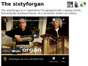
This is the story of how I built a remote control system for my computer and speakers. It is based on an off-the-shelf universal remote and some AVR chips and other electronics.
The problem
My computer speaker system, called Creative Inspire T6060, was giving me some trouble. It's one of those that come equipped with a tethered remote-control thingy, and the volume wheel was beginning to show signs of an aging graphite potentiometer, meaning pops, cracks and occasionally unstable volume levels. Furthermore, the way my furniture was organized, it was impossible to change the volume (or pause, or anything) from the sofa when watching a movie. In other words, some kind of remote control solution was called for.
Reverse-engineering the volume controller
The first step was to open up the volume control box. Of course, reverse-engineering is like a box of chocolates — you never know what you're gonna get. In this case, I was lucky enough to find a clean system that could be quickly analysed by just looking at the PCB layout.
 |  |
 |  |
As I had hoped, the volume wheel was simply a potentiometer connected as a voltage divider, providing the base unit with a voltage level between 0 and 5 volts. The volume control box was powered (with 9 volts DC), which was also going to be useful.
Producing a volume signal
I connected an AVR ATmega88 to a resistor ladder, so that a 6-bit output value would be converted into a voltage level between 0 and 5 volts. Originally, I also routed this signal through an OP amp to keep the impedance down, but further experimentation showed that this was unneccessary. Then I added a rotation sensor as an input, so that I could adjust the volume by turning a knob. Since the rotation sensor is digital (it emits a pulse train as you turn it), it won't age like the old volume wheel.
 |  |
 |  |
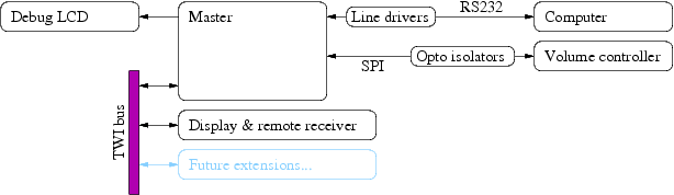
Once this was up and running, I wanted to be able to read out the current volume setting digitally, and be able to change it as well. Since the AVR controller was powered by the speaker system (using the aforementioned 9 volt supply), I decided to add some kind of opto-isolated communications port. I ended up using the SPI protocol (the one you use when programming an AVR chip through the MISO/MOSI/SCK pins), because it's easy to opto-isolate uni-directional signals. I then connected a second ATmega88, powered separately, to the other end of the opto isolators, and designed a rudimentary high-level protocol.
At this point, I ran into a problem: Whenever the volume was set to a medium (or high) level, the speakers would hum or purr softly. I had designed the communication protocol so that the "master" (the second ATmeta88 chip) would poll the volume controller chip several times per second, and apparently the LEDs used in the opto-isolated communication was drawing a noticeable, varying amount of current from the speaker system. In the end, I managed to connect a capacitor in such a way as to flatten the current curve, and the humming disappeared.
Decoding an IR signal from a remote control
A typical remote control transmits signals according to a simple serial protocol over a 38 kHz bearer. By connecting an IR receiver module (basically an IR light sensitive diode and a 38 kHz filter) to the master chip, I was able to decode the signals generated by my universal remote control. Then it was just a simple matter of mapping the volume buttons on the remote control into control signals to send over the opto-isolated link to the volume controller.
Display
The display runs on a separate ATmega88. It consists of two 7-segment LED modules and three discrete LEDs. The idea is that when you change the volume, the display lights up with the new volume level for a few seconds. I decided to move the IR receiver from the master chip to the display controller as well. The display controller is a really simple AVR project, so I won't describe it in detail. It communicates with the master using TWI (an I²C variant supported natively by the AVR chips).
 |  |
 |  |
Computer communication
Finally, the master communicates with my computer using RS232. I have a daemon process running on the computer, listening for commands on a unix socket. Currently, I've defined commands for setting the volume and for switching the three discrete LEDs on or off. A command line interface, consisting of two client programs called volume and lamp, can be used to send commands to the daemon.
The daemon process also receives remote control events from the master whenever a remote control button has been pressed. These events are turned into keyboard events using the /dev/uinput mechanism in Linux, and the mapping has been set up so that I can control mplayer and ogle using the standard buttons (play, pause, etc.) on the remote control. In the future, I intend to write some kind of movie selection interface as well, which will enable me to navigate through my media files from the sofa.
Final words
It's always fun to experiment with home automation, to reverse-engineer and to connect various gadgets in unintended ways. I hope this post will inspire more people to tinker with their electronics. But remember that it's your own fault if anything breaks. =)
Posted Friday 26-Oct-2007 16:39
Discuss this page
Disclaimer: I am not responsible for what people (other than myself) write in the forums. Please report any abuse, such as insults, slander, spam and illegal material, and I will take appropriate actions. Don't feed the trolls.
Jag tar inget ansvar för det som skrivs i forumet, förutom mina egna inlägg. Vänligen rapportera alla inlägg som bryter mot reglerna, så ska jag se vad jag kan göra. Som regelbrott räknas till exempel förolämpningar, förtal, spam och olagligt material. Mata inte trålarna.
Fri 8-Aug-2008 07:01
21 more comments hidden. Click to show all.
Wed 18-Jan-2017 21:28
Maybe replacing the broken Potentiometer with this one:
RV12 10K 103 B103 Switch Rotary Radio Potentiometer
Hope this helps.
Tue 11-Jul-2017 07:52
Tue 2-Jan-2018 20:03
Sun 21-Jan-2018 18:36