
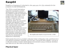

Turbulence source code
Greetings to kuroneko at the Propeller forum for solving the reverse engineering challenge! Here is the source code, as promised.
On this page you'll find the complete source code for Turbulence, as well as a general overview and discussion of some of the techniques I used.
The entire demo is written in Propeller assembly language (PASM), making heavy use of the extended syntax introduced in plasma. Plasma and Turbulence evolved together.
Download the source code
- turbulence-src (Source code, 60.2 kB)
You will have to download plasma as well, in order to build.
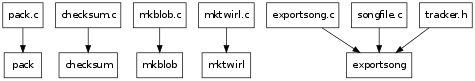
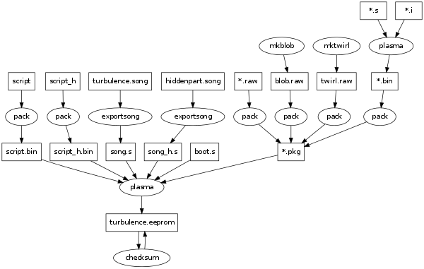
Overview of the build process
This is what the Makefile is set up to do:
Cog deployment
The cogs are deployed like this:
- 0. Booting, unpacking, initialization, script, music sequencing.
- 1. Visual effects.
- 2. Visual effects.
- 3. Visual effects.
- 4. Visual effects.
- 5. FM synthesizer with stereo spatialization.
- 6. VGA driver.
- 7. VGA driver.
Once initialization has completed, cogs 0, 5, 6 and 7 will keep running the same software for the entire duration of the demo. Cogs 1, 2, 3 and 4 will be reloaded with new effects according to the script.
Memory maps
At boot, the entire EEPROM is copied into hub RAM. However, the initialization code only depends on the first 0xd8 bytes, as well as a few kilobytes of compressed data in the middle of RAM. Post-initialization loading will happen over the I²C bus.
Once the demo is up and running, this is how the hub RAM is allocated:
Hub RAM:
========

0000-73ff       29k     Graphics buffers and miscellaneous effects data.

        0000-39ff       14.5k   128x116 pixel buffer
        3a00-73ff       14.5k   128x116 pixel buffer

7400-7bff       2k      Cog unpack area.
7c00-7cff       256b    Palette.
7d00-7dff       256b    Extra effects buffer (e.g. texture).
7e00-7ea7       168b    Channel data for playroutine (6 channels x 28 bytes).
7ea8-7f63       188b    Frequency table (constant) for playroutine (94 words).
7f64-7f7f       28b     Global variables for inter-cog communication.
7f80-7fff       128b    Buffer for realtime audio visualization (32 longs).
As you can see, this is completely unrelated to the structure of the EEPROM:
EEPROM:
=======

0000-001b       28b     Spin header.
001c-00d3       184b    Bitstream reader and unpacker. Also contains file table pointer.
00d4-00d7       4b      Final instruction of boot loader (overwritten).
00d8-00eb       20b     Banner to encourage reverse engineering.

...                     Bitfield packed music data (corresponding RAM area used to unpack init, play & vga cogs).
...                     Compressed init, play & vga cogs, beyond the 2k boundary so can be unpacked from RAM.
...                     Compressed code and data.

                64b     File table. Points to compressed files in EEPROM.
                18b     Alternative file table for hidden part.

...                     Padding.
During initialization, cog 0 will be reloaded twice as more code is unpacked. This is how the cog registers are allocated during each of the three phases:
COG 0:
======

BOOT phase:
        0-6     7       Spin header (re-used as variables).
        7-52    46      Bitstream reader and unpacker.
        53      1       Final instruction to launch unpacked INIT.

INIT phase:
        0-6     7       Scratch variables.
        7-52    46      Bitstream reader and unpacker.
        53-111  59      EEPROM routines.
        112-            Initialization code (initialize globals and frequency table, verify EEPROM, launch vga & play).

PLAY phase:
        0-6     7       Scratch variables.
        7-52    46      Bitstream reader and unpacker.
        53-111  59      EEPROM routines.
        112-            Playroutine & script parser.
The EEPROM routines are needed during the INIT phase in order to verify that the demo is in fact stored in the EEPROM. This is done by reading and verifying a few bytes of EEPROM, including the checksum byte. In the PLAY phase, the EEPROM routines are used for accessing music, script and compressed data.
Parallel graphics: The overlay technique
I/O pins P0-P7 are used as an internal video bus. Cogs 1-4 can transmit video on these pins, either by writing to OUTA directly, or by setting up their video generators to do it.
Cogs 6 and 7 generate the actual vga signal. Each cog samples an internal video line during 1.5 vga lines (240 internal pixels, 16 clocks each, 3840 cycles out of 5080), performing colour table lookup before packing the pixels into an internal scanline buffer. It then transmits the scanline buffer twice. The two cogs do this in an interleaved fashion. This yields an external resolution of 240x480 pixels at vga rate (8 cycles per pixel). Internal video generation can work with 240x240 at a much lower rate, namely 16 cycles per pixel and 5080 cycles per line, with the added benefit of indexed colours.
This is an illustration of the tight loop (vga.s) in which cogs 6 and 7 sample the internal state of I/O pins P0-P8 (P8 being held low at all times) and do the colour table lookup:
        0               movs    --.            <-- sample
        1         .->   store     |
        2         |     mov     <-'
        3         `--   d++
        4               movs    --.            <-- sample
        5               <<        |
        6               or      <-'
        7               nop
        8               movs    --.            <-- sample
        9               <<        |
        10              or      <-'
        11              nop
        12              movs    --.            <-- sample
        13              <<        |
        14              or      <-'
        15              djnz
The colour table is stored in cog registers 0-255, and is refreshed from hub RAM (0x7c00) during each vertical blanking period.
The vga cogs also update a hub RAM variable with the predicted system timer value at which the next frame will start. Cogs 1-4 read this variable in order to sync up with the vga cogs, which is necessary in order to get a stable internal video frame.
Dithering
Some effects, such as the text overlays, render directly to the internal video bus. Other effects are divided into several cogs: One or more producers, which render to a hub RAM frame buffer (typically 128x116, one byte per pixel), and a consumer which reads pixels from the frame buffer and transmits them onto the internal video bus.
In particular, one of these consumers (viewdither.s) is responsible for dithering. In this case, the pixels in the framebuffer can be though of as bit fields, BBBBOOOO, where B is a base colour index and O represents a linear interpolation between this colour and the next one in the palette (B + 1). For each incoming pixel, the ditherer will add a random number in the range 0-15, and then shift the pixel value four bits to the right. This way, the probability of ending up with B + 1 rather than B varies linearly with the value of O.
As you can see in the source code, this calculation is performed twice (with different random numbers) with four pixels at a time, in order to generate eight internal video bus pixels from four frame buffer pixels. To prevent overflow between adjacent pixels within the same 32-bit word, no byte in the frame buffer may be greater than 0xf0.
There is another dithering mode where pixels are stored in the frame buffer as BBOOOOOO. In this case, the random number is in the range 0-63, and the sum is shifted six bits to the right. This is useful when you just need a smooth transition between a few colours, which is the case with e.g. the clouded sky and the mandelbrot zoomer.
Parallel computation
Some effects, notably the mandelbrot zoomer and the voxel landscape, lend themselves to parallel computation. The cogs are set up with a consumer (viewdither.s again) and several producers. In this case, the consumer will also take on the role of a job dispatcher. A shared hub RAM variable (called nextline) is protected by lock 0. This variable is initialized by the consumer. The producers take turns reading and incrementing (atomically, using the lock mechanism) this variable, in order to fetch jobs. A job typically corresponds to one display line (or column, for the voxel landscape). When a job is completed, the producer fetches another one through the shared variable. When the variable has reached its limit (the total number of lines), an entire frame has been rendered. The consumer, acting as job dispatcher, takes charge by swapping the back and front buffer pointers and resetting the shared variable. The producers notice this, and begin fetching jobs for the next frame.
Final words
I had a lot of fun writing Turbulence, and I think I invented a bunch of new techniques, most notably the internal video bus mechanism for inter-cog graphics overlays. It is my hope that the source code will be useful and inspiring to others, so feel free to copy any part of it for your own projects.
Posted Monday 11-May-2009 16:47
Discuss this page
There are no comments here yet.