


Platform Hopping
Let's recreate the sound of the 8-bit Nintendo Entertainment System on a C64!
Download
- lft-platform-hopping.prg (C64 executable, 8.3 kB)
- Linus Akesson - Platform Hopping.mp3 (MP3, 4.3 MB)
Introduction
The SID chip (Sound Interface Device) in the Commodore 64 has three channels, which means that it can play up to three sounds at the same time. A channel can be individually configured to play any one of the supported sounds, such as pulse wave, triangle wave, or white noise.
In contrast, the APU (Audio Processing Unit) of the NES (Nintendo Entertainment System) offers five fixed-function channels: Two pulse-wave channels, one triangle-wave channel, one noise channel, and one channel for sample playback.
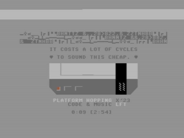
My contribution to the music compo at X 2023 was a C64 program that plays a very NES-like piece of music. A large part of the NES feeling comes from the composition itself. The genre is perhaps best described as “uptempo anime opening theme” with the occasional famichord thrown in for good measure. I've also refrained from pulse-width modulation and kept the volume envelopes simple. But as suggested by the cheeky Dolly Parton reference, “It costs a lot of cycles to sound this cheap”, there is also a technical aspect.
In this article I'll take you through how the program works. If you want to understand every last detail, it helps if you have experience with machine-code programming. But readers with only a general technical interest can still enjoy the ride, and might be surprised at just how many different techniques are involved, and how esoteric they are (here, esoteric is a euphemism for bat-shit crazy).
None of the following hacks are new. On the contrary, they are well-established techniques in the C64 demoscene, but they are relatively advanced techniques. Most C64 coders prefer to stay away from them and retain their sanity.
Overview and channel mapping
Pulse waves are prominent in both NES and C64 music, and frequently used for melodies. Since we can't compromise on such a central part of the overall sound, we'll allocate one SID channel each to the two NES pulse-wave channels. Well, almost: These two SID channels will also accomodate the NES noise channel. Noise is typically used for cymbals and hi-hats whereas complex drum sounds like snare drums are better served by the NES sample channel.
A brief noise burst sounds like a hi-hat and can be played at the same time as a pulse-wave note in order to accentuate its attack. We can emulate this effect by instead replacing the first few milliseconds of a note by noise. Technically, we're delaying the start of the musical note slightly, but this isn't noticeable. As for longer cymbal hits, well, we just have to use them sparingly and compose the music in such a way that one of the pulse channels is free on those occasions.
The SID allows the pulse width (duty cycle) of the pulse waveform to be set freely, whereas on the NES, only a handful of pulse widths are supported. When composing the music, we can easily limit ourselves to these pulse widths in order to mimic the overall sound of NES music. More problematically, the NES APU allows the volume of the pulse waveform to be changed freely, whereas on the SID we have to play by the rules of the built-in envelope generator. But in practice, a lot of NES music uses simple envelopes that are easy to mimic on the SID.
This leaves only a single SID channel for both triangle waves and samples. Now, ostensibly the SID doesn't support sample playback at all, but people have figured out several ways to achieve it anyway. The so called SounDemoN method (named after its inventor) offers 8-bit sample playback on a single SID channel, albeit at the cost of a lot of processing power.
The playback rate of the NES sample channel is configurable but rather inflexible: There's only a handful of frequencies to choose from, and they are not related to a musical scale. Therefore, the playback rate is typically held constant and the channel is only used for drums and sound effects. That is fortunate for us, as working with a constant sample rate is much easier than having to accomodate different pitches.
But this still leaves us with the triangle wave. On the NES, the triangle has a very characteristic sound because of its low resolution. It looks a bit like a staircase:

Because of this low resolution, we can actually afford to synthesize the waveform in software on the C64, and mix it in realtime with the output from the emulated sample channel. There's a drawback: Our chosen method for sample playback on the SID is going to operate at the relatively low playback rate of about 8 kHz. This will introduce aliasing into the overtone-rich staircase wave. But if we limit ourselves to playing only bass notes on the triangle channel—and conveniently for us this is a common practice in NES music—the aliasing won't be too egregious.
Thus, to recap: Two of the SID channels will be used to implement the NES noise and pulse channels. This part is easy to pull off because the SID chip provides all the necessary functionality. The third SID channel will implement the NES triangle and sample channel using a combination of software synthesis, software mixing, and a clever but CPU-intensive technique for sample playback. This is the tricky part, so let's dive in!
Sample playback: The SounDemoN method
Each SID channel contains a digital oscillator that drives a couple of waveform generators. The output from one of these waveform generators, selected by the programmer, is converted to an analogue voltage which is then attenuated by an envelope generator using a multiplying DAC (Digital to Analogue Converter). Thus, what comes out of the DAC is the waveform, at the proper volume, as an analogue voltage. The outputs from the three DACs are then combined using a high-impedance mixer inside the chip.
The SID channel control register has a separate enable-bit for each waveform generator: There's one bit to enable or disable the pulse wave, another bit for the triangle wave, one for the sawtooth wave, and one for the noise wave. People discovered quite early that you could enable several waveform generators at the same time to obtain a handful of extra sounds (“mixed waveforms”). But it took several decades for somebody to notice a very cool hidden feature:
If you disable all of the waveform generators, nothing drives the output. The analogue signal that is routed through the DAC just floats. It will eventually drain back to ground level, but this happens relatively slowly because of the high-impedance mixer input. Therefore, if you let the oscillator run, you can wait until one of the waveform generators reaches a desired value and briefly enable it; this will immediately set the output signal to that value—the first sample. Then you can disable the waveform generator, and the output signal will remain at the same voltage even though the oscillator keeps running. At a later time, you enable the waveform generator again, and its output is transferred to the analogue signal. This becomes the second sample. In other words, there's an accidental sample-and-hold circuit built into each SID channel.
To make this useful, we must control the oscillator in such a way that if we enable the waveform generator briefly at regular intervals—the sample playback rate—it will output exactly the sequence of sample values that we want to play, one at a time.
The oscillator is a 24-bit accumulator. On every clock cycle, the current pitch of the channel (which is under the programmer's control) gets added into the accumulator. The uppermost bits of the accumulator are continually sent to the waveform generator where they are transformed to the desired soundwave. The simplest case is the sawtooth generator: It just passes the eight most significant bits of the input to the output. As the value in the accumulator gets larger, the output from the sawtooth generator increases, and when the accumulator wraps around, the sawtooth waveform also jumps back to zero. Therefore, if we could put any value we wanted into the eight upper bits of the accumulator, we could also send that 8-bit value to the sample-and-hold circuit by briefly enabling the sawtooth waveform generator.
But there's a snag: We can't just write an arbitrary value to the eight upper bits of the accumulator. In fact, we have no direct control over the accumulator at all, with one crucial exception: The SID channel control register contains a so called test bit. When this bit is set, the accumulator is immediately reset to zero and held there. When the bit is cleared, the oscillator resumes normal operations, i.e. adding the current pitch value on every cycle. We have control over the pitch value, but unfortunately this is only a 16-bit quantity. In order to manipulate the upper bits of the accumulator, we have to set the pitch to a large 16-bit number, and then wait for enough of these values to add up.
As inconvenient as that is, we can actually use this technique to make the oscillator reach any value we want. First, we store the desired value in the upper byte of the pitch register. Then we reset the oscillator using the test bit, release the test bit again, and wait for 256 clock cycles. At this point, the accumulator contains 256 times the pitch value—we have shifted our desired sample value into the top eight bits of the 24-bit accumulator. And exactly when that happens, we briefly enable the sawtooth waveform. Heureka! By following this procedure over and over at regular intervals, we can play samples.
But what playback rate can we achieve? We have to wait for 256 cycles per sample, and the act of resetting the oscillator takes a few cycles in addition to that. But to keep the calculations simple, let's sacrifice some of the highest values and assume that we can complete the entire procedure every 256 cycles. On a 1 MHz machine, that would give us a maximum playback rate of about 3900 Hz, which would result in rather poor sound quality.
But there's a better way: The triangle waveform (remember, this is the SID, so it has a proper high-resolution triangle wave) rises twice as fast as the sawtooth waveform. If we use the triangle waveform, we only need to wait for 128 cycles to reach the highest value. And if we can run the entire procedure in 128 cycles, we can play samples at 7800 Hz. Now we're talking!
Timer interrupts
If we run the above procedure every 128 cycles, and the procedure itself takes 128 cycles, then it figures that there would be no clock cycles left for anything else. But we need to do other things with the CPU, such as generating the sample data to play.
Most of these 128 cycles consist of waiting. We could fill those cycles with code that performs useful work, and this is where timer interrupts come in handy.
There are four independent timers in the C64, and they can all be configured to trigger interrupts at regular intervals. We just need one—for now. As most of you know, an interrupt causes the CPU to pause whatever it's doing and jump to a particular address instead, where you've placed some code to handle the interrupt. That code ends by telling the CPU to resume what it was doing when the interrupt occurred.
So we'll configure a timer to generate an interrupt every 128 cycles. Earlier, we described the sample playback code as something that would prepare the oscillator, then wait, and finally emit the sample. Conceptually, we will now have to invert this shape: The interrupt handler should first emit a sample, then immediately prepare the oscillator for the next sample, and then return. The timer will fire another interrupt when it's time to emit the next sample.
The interrupt handler
Below is a first attempt at an interrupt handler. It uses self-modifying code in two places: To preserve the previous contents of register A (so we can use it without disturbing the code that was interrupted), and to keep track of the next position in the audio buffer. Self-modifying code is rarely useful on modern computers because the instruction cache gets in the way, but it's a bread-and-butter technique on 8-bit systems that don't have caches.
int_handler
        sta     savea+1         ; store register A, because we will overwrite it
        lda     #$11
        sta     $d412           ; briefly enable the triangle waveform
        lda     #$01
        sta     $d412           ; disable all waveforms
        lda     #$09
        sta     $d412           ; reset and stop the oscillator
ptr     lda     audiobuffer	; get next sample
        sta     $d40f           ; set upper byte of pitch
        lda     #$01
        sta     $d412           ; resume oscillator
        inc     ptr+1           ; modify operand, incrementing pointer to next sample
        lda     $dd0d           ; acknowledge the timer interrupt
savea   lda     #0              ; restore register A (it was saved inside the instruction)
        rti                     ; return from interrupt
Between interrupts, the main program can go about its business, figuring out what notes to play and preparing sample data for the interrupt handler to pick up.
After mixing the sample channel with the low-resolution triangle waveform, we're going to compress the sound to increase the loudness. For this we'll use a precomputed table of 8-bit values representing a non-linear function (y = x^0.8) to saturate the signal. It turns out to be convenient to perform this table look-up in the interrupt handler, rather than in the routine that fills the audio buffer, so let's add it now. Typically such a table look-up would be performed like this:
ptr     ldx     audiobuffer     ; put the original sample in the X register
        lda     compress,x      ; load entry number X from the table
However, any register that we use in the interrupt handler must be saved and restored, otherwise whatever code is executing in main context would crash. Saving and restoring register X would set us back six cycles. But there's a better way: Instead of using register X, we can use self-modifying code:
ptr     lda     audiobuffer     ; get original sample
        sta     mod+1           ; store as low byte of operand in next instruction
mod     lda     compress        ; the 'compress' table must be page-aligned
The extra sta has an overhead of four cycles, which is better than six.
With the compression look-up, our complete interrupt handler takes 63 clock cycles to run. We can squeeze that down to 60 by putting the code on the zero-page. The zero-page (RAM in the address range $0000–$00ff) is typically used for variables, but nothing prevents us from running code there. Executing from zero-page doesn't speed up the code in and of itself, but it allows us to use a faster addressing mode for the self-modifying instructions.
Badlines
There is a complication: Whenever the video chip of the C64 is about to display a new row of text—this happens on every eighth row of pixels during the visible portion of the screen—it needs to fetch new character data from memory. In order to do that, it pauses the CPU for 43 clock cycles. If our timer expires at some point during these 43 clock cycles, the interrupt handler will have to wait until the CPU can run again. But during this time, the SID channel accumulator will keep on accumulating, and when a sample is finally emitted it will have the wrong value.
To prevent this, we can make sure that the timer interrupt doesn't fire on so called badlines—the places on the screen where the CPU is paused. One line of video on a PAL machine lasts for 63 cycles, and there are 312 rasterlines in a video frame. The actual position of the badlines on the screen is configurable (to support scrolling) but if we stick with the default screen mode, badlines only occur on odd-numbered rasterlines.
Thus, we could once more sacrifice a few values from the output range, and run the timer interrupt every 126 cycles (instead of 128), which corresponds to exactly two rasterlines. By starting the timer near the beginning of an even rasterline, we can be sure that every subsequent interrupt likewise occurs near the beginning of an even rasterline, and therefore that the interrupt handler won't interfere with the badlines. This is how we could start the timer at the beginning of the program:
        lda     #$fe            ; an even line number
wait    cmp     $d012           ; compare with the current-line register
        bne     wait            ; branch back to 'wait' until equal
        lda     #$11
        sta     $dd0e           ; (re)start the timer
Filling the audio buffer
The interrupt handler consumes one byte from the audio buffer every 126 clock cycles, resulting in a sample rate of 7819 Hz. Thus, the code running in main context must be able to produce new sample data at the same rate. We'll use two audio buffers: one for reading and one for writing. Immediately after the interrupt handler has consumed the final byte in a buffer, we swap the buffer pointers (from main context).
For convenience, let's synchronize the tempo of the music with the video frame rate. We'll execute a playroutine—the code that decides what notes to play—once per frame, at a fixed on-screen position, and use whatever CPU time is left to compute the samples and write them to one of the audio buffers. Since there are 312 rasterlines in a frame and we consume a byte every two rasterlines, each buffer will contain 156 sample values. Recall that the interrupt routine contains a buffer pointer (inside a 16-bit operand), but it only increments the low byte of this pointer. By using the last 156 bytes of a page for audio data, we can check if this low byte has wrapped around to zero, and that's when we swap the buffers.
The structure of the code running in main context is:
main
        ldx     #>audiobuf2     ; put high byte of address in register X
        ldy     #100            ; first index within the page, i.e. 256 - 156
wait1   lda     ptr+1           ; check low byte of operand in interrupt handler
        bne     wait1           ; loop until zero
        sty     ptr+1           ; replace low byte of operand
        stx     ptr+2           ; replace high byte of operand

        ... call playroutine and fill audio buffer 1 while playing buffer 2 ...

        ldx     #>audiobuf1
        ldy     #100
wait2   lda     ptr+1
        bne     wait2
        sty     ptr+1
        stx     ptr+2

        ... call playroutine and fill audio buffer 2 while playing buffer 1 ...

        jmp     main
Astute programmers may have spotted what looks like a race condition in this code. We use two separate instructions to modify the low and high bytes of the current read-pointer. What if a new interrupt is triggered between these instructions? Shouldn't we disable and re-enable interrupts around the critical section? But that won't do. Remember: If we delay the handling of the interrupt in any way, the wrong sample value will come out. Instead we have to guarantee, statically, that no new interrupt is due at this point.
Normally there's a pretty large gap—about one rasterline—between two successive invocations of the interrupt handler, which leaves plenty of time for us to busy-wait for a zero in ptr+1 and update the two bytes. But if that rasterline happens to be a badline, where the CPU is stalled for 43 cycles, we have a problem. However, because we've chosen an audio buffer size that matches the video frame rate, our busy-wait code will always run at a fixed location on the screen. If it happens during the non-visible portion of the frame, where there are no badlines, we can be sure that the critical section won't be interrupted. Thus, all we need to do is wait for the end of the visible portion of the screen before starting the timer in the first place (and this was actually shown in the code snippet in the section about badlines).
The playroutine itself is a fairly standard SID player that reads structured note data from memory and updates the SID registers, at least for the first two channels. But drum triggers and the desired pitch of the triangle channel are stored in variables (and emitted one frame ahead of time to compensate for the buffering). We'll now take a look at the code that reads those variables and computes the values that go into the audio buffer.
The bulk of the code will run from the zero-page, to speed up the self-modifying instructions. It looks like this:
        ldy     #100
        ldx     lowphase

loop    txa                     ; copy register X to register A
lsb     sbx     #0              ; X := (X & A) - operand
        lda     hiphase+1
msb     sbc     #0              ; subtract with carry
        sta     hiphase+1

hiphase lda     wavetable       ; read from triangle wave table
        clc                     ; clear carry
samp    adc     s_blank,y       ; add sample data
dest    sta     audiobuf1,y     ; and store into buffer

        iny
        bne     loop

        stx     lowphase
Register Y is the loop index, running from 100 up to 255. The current 16-bit phase of a software-implemented oscillator is stored in two parts: The low byte is kept in the X register (and in the variable lowphase between calls), while the high byte is kept in hiphase+1, the low byte of an operand that points into a 256-byte table containing a staircase triangle wave. Remember, this code is on the zero-page so the operand byte can be accessed quickly.
For each sample, the phase is updated by adding a 16-bit pitch value to it. This value is stored in the operands at lsb and msb. The instruction sbx is a so-called illegal opcode, an unintended but useful instruction in the 6502 processor with somewhat quaint behaviour: It computes the bitwise-and of registers A and X, subtracts a constant operand (without carry), and stores the result into register X. The useful part in this case is the ability to subtract a constant from register X, but we don't need the bitwise-and. Thus we first copy X to A, because a number “and” itself evaluates to the same number.
Since we run the playroutine once per audio buffer, the drum samples will always line up with the buffers. A drum sound may span across several buffers, but we can arrange the data across multiple pages where we only use the last 156 bytes of each page. That way, we can reuse the Y register as an index into both the sample data and the audio buffer.
But we will have to update the high byte of the operand at samp between calls to this routine, just as we have to update the operands at lsb and msb to store the desired triangle pitch. This is handled on every frame after invoking the regular playroutine, but before calling the above code on the zero-page. A pitch value of zero will stop the oscillator and silence the triangle channel. Finally, the instruction at dest is also modified between calls, so we can reuse the same routine for both audio buffers.
Jitter correction
We've set things up so that badlines won't interfere with our timer interrupts, because the SounDemoN sample playback method is very sensitive to delays. But dodging the badlines isn't enough! The timing needs to be exactly right when we briefly enable the triangle waveform, otherwise the wrong sample value is emitted. And unfortunately there is another source of jitter when an interrupt occurs: The CPU won't handle the interrupt until it has finished executing the current instruction. Instructions take anything from two to seven cycles to complete and the timer interrupt can happen at any time, i.e. in the middle of an instruction. This leads to a variance of six cycles in the interrupt response time. There's also a quirk in the CPU that prevents an interrupt from being handled just after a branch instruction (under certain conditions). This adds an extra variance of two cycles.
In other words, if we define cycle 1 as the earliest possible time that our interrupt handler could start to execute, then in practice it may start on any cycle in the range 1–9. We will have to compensate for this at the beginning of the interrupt handler, by measuring how late we're running and delaying for the appropriate number of cycles.
It's easy to determine how late we're running, because we can read the current value of the hardware timer. The timer is repeatedly counting down from 125, firing an interrupt every time it underflows. So ideally if we read the value near the beginning of the interrupt handler, we'd get something close to 125, minus the number of cycles of delay caused by the jitter. In practice, the maximum value will be less than 125, because both the processor and the timer chip itself (depending on the chip version!) will add a fixed delay, but we can easily take that into account.
The important thing is that we can use the difference between the maximum timer value and the observed timer value to compute the precise delay, in cycles, that will make the rest of the interrupt handler execute at regular intervals, exactly 126 cycles apart.
To implement a variable delay, we can use a clock slide. This is a series of timed no-operation instructions that can be entered at an offset. On a machine with single-cycle instructions, the implementation would be straightforward: String together a bunch of single-cycle instructions and jump to any place in the string. The number of instructions following the jump will determine the total delay. On the 6502, all instructions take at least two cycles, so we have to get a little creative:
        lda     #$a9    ; a9 a9
        lda     #$a9    ; a9 a9
        lda     #$a9    ; a9 a9
        lda     $eaa5   ; ad a5 ea
The above code takes 10 cycles. Two for each lda # instruction, and four for the final lda that reads from an absolute address. If we skip two, four, or six bytes, it's easy to see that we reduce the delay by two, four, or six cycles, respectively. But if we skip just one byte, the CPU will decode a different sequence of instructions. What used to be operands will now be opcodes:
        lda     #$a9    ; a9 a9
        lda     #$a9    ; a9 a9
        lda     #$ad    ; a9 ad
        lda     $ea     ; a5 ea
Again, each lda # takes two cycles, but the final lda uses a different addressing mode (absolute zero-page) and executes in three cycles. The total execution time is down to 9 cycles, and we can again skip two, four, or six bytes to reduce the delay accordingly.
The final case is when we skip a full eight bytes into the clock slide. Then, only a single byte remains:
nop ; ea
And nop is a two-cycle instruction. The complete jitter compensation routine looks like this:
        lda     #...    ; put the highest possible timer value here
        sec             ; set carry
        sbc     $dd04   ; subtract the actual timer value. A becomes 0..8
        sta     delay+1 ; modify the branch offset
delay   bpl     slide   ; branch into the clock slide
slide   lda     #$a9
        lda     #$a9
        lda     #$a9
        lda     $eaa5
        ; now we're synchronized!
At this point, it seems that we have all the necessary functionality in place. But if we put all of these routines together and run the program, the music will play, but it will stutter. It turns out that our code is too slow!
Time to optimize.
Acking the interrupt with style
We can shave off one clock cycle from the interrupt routine using a cute hack. Towards the end of the routine (the first code example on the page), you may have noticed that we are loading a byte from address $dd0d, but we're not using that byte. This is the timer interrupt flag register, and the act of reading the register acknowledges the interrupt which makes it possible for the timer interrupt to fire again. Reading this register takes four clock cycles, but there's a way to reduce it to three.
On the 6502 CPU, instructions occupy one, two, or three bytes. The first byte, the opcode, determines what to do. The other bytes (if present) contain a parameter (operand). After fetching the opcode, the CPU must decode it to figure out what to do, including whether to fetch an operand or not. But decoding takes time, and on the second clock cycle the CPU doesn't know yet whether an operand will follow the opcode. So in the interest of speed, the 6502 will always read the byte immediately following the opcode just in case it's going to be needed.
The RTI instruction (ReTurn from Interrupt) has no operand; it is a single-byte instruction. But because of the above quirk, when the CPU executes an RTI, it also reads the byte following the instruction, and throws away the value. Just before the interrupt flag register, at address $dd0c, is another hardware register used for serial communication. Since we don't use serial communication in this program, we can use the register as a normal memory location, and store the RTI opcode there.
But our code is executing on the zero-page, not in the hardware register area. We have to end the routine with a jump to address $dd0c in order to execute the RTI there and, as a side effect, read from address $dd0d and acknowledge the interrupt. The jump takes three cycles, but we no longer need the four-cycle lda, for an overall gain of one cycle.
By now, our complete interrupt handler looks like this:
int_handler
        sta     savea+1         ; store register A, because we will overwrite it

        lda     #...            ; put the highest possible timer value here
        sec                     ; set carry
        sbc     $dd04           ; subtract the actual timer value. A becomes 0..8
        sta     delay+1         ; modify the branch offset
delay   bpl     slide           ; branch into the clock slide
slide   lda     #$a9
        lda     #$a9
        lda     #$a9
        lda     $eaa5

        ; now we're synchronized!
        lda     #$11
        sta     $d412           ; briefly enable the triangle waveform
        lda     #$01
        sta     $d412           ; disable all waveforms
        lda     #$09
        sta     $d412           ; reset and stop the oscillator
ptr     lda     audiobuffer     ; get original sample
        sta     mod+1           ; store as low byte of operand in next instruction
mod     lda     compress        ; the 'compress' table must be page-aligned
        sta     $d40f           ; set upper byte of pitch
        lda     #$01
        sta     $d412           ; resume oscillator
        inc     ptr+1           ; modify operand, incrementing pointer to next sample

savea   lda     #0              ; restore register A
        jmp     $dd0c           ; jump to RTI instruction, acknowledge as a side-effect
But it's still not fast enough!
Distributed jitter correction
As elegant as the clock slide may be, it does require some overhead. The delay inside the slide itself is pretty much inevitable, but before we get there we have to read a timer register, perform a subtraction, modify an instruction, and finally jump. There's a better way, but it's not for the faint of heart. This is the so called Ninja method (named after its inventor) for distributed jitter correction.
When an interrupt occurs, the CPU reads a special location, a vector at address $fffe–$ffff, to find out where the interrupt handler is located in memory. So far, this has been an address on the zero-page, but the point is that we can place the interrupt handler anywhere we want.
The idea, now, is to create nine different delay routines, each ending with a jump to a common routine on the zero-page (the bulk of the interrupt handler). We'll include the saving of register A as part of the delay routines. The shortest delay only contains the saving and the jump itself:
        sta     savea+1         ; write to zero-page, 3 cycles
        jmp     int_common      ; jump, 3 cycles
The next routine achieves the same thing in one more cycle (the “!” syntax forces the assembler to use a full 16-bit operand even when the target is on the zero-page):
        sta     !savea+1        ; write to absolute address, 4 cycles
        jmp     int_common      ; jump, 3 cycles
The remaining seven routines are variations of the above prefixed with nop instructions, so the longest delay routine (14 cycles) looks like this:
        nop                     ; no operation, 2 cycles
        nop                     ; no operation, 2 cycles
        nop                     ; no operation, 2 cycles
        nop                     ; no operation, 2 cycles
        sta     savea+1         ; write to zero-page, 3 cycles
        jmp     int_common      ; jump, 3 cycles
Now we need to divert the CPU into an appropriate delay routine based on the current value of the timer register. The fastest way to jump to a dynamic location based on the value of a register is to have the register located inside the operand of the jump instruction.
A jump instruction consists of three bytes: $4c, the low byte of the target address, and the high byte of the target address. Meanwhile, the timer register consists of a low byte (at most 125 and decrementing on each cycle) and a high byte (zero).
Our delay routines are several bytes long, so they have to be placed some distance apart in memory. That means we can't use the low byte of the timer directly as the low byte of the jump instruction; the changing value will have to go into the high byte. Thus our delay routines will have to be placed one page apart, occupying a total of nine consecutive pages in memory.
The high byte of these addresses would be a little less than 125, so we'd have to put our delay routines right in the middle of the address space, somewhere in the $7000-$7fff range. While this would work for our music player, it is often inconvenient in a larger demo context. But the C64 has four timers in total. So when distributed jitter correction is used, the conventional approach is to set up a separate timer that runs in tandem with the timer that generates the interrupts, but at a constant offset. This allows us to place the chunk of nine pages anywhere we want.
And so, the timer at $dc06 will provide the high byte of the operand of a jump instruction. The timer at $dc04 will be stopped and held at a constant value of $004c. Here's an overview of the registers:
dc04    4c
dc05    00
dc06    (variable)
dc07    00
...
dd04    (variable)
dd05    00
We'll set the interrupt vector at $fffe to point to $dc04 in the hardware register area. When an interrupt occurs, the CPU will start executing the jmp instruction ($4c) leading to the appropriate delay routine, which then delegates to the common interrupt handler at exactly the right moment.
This is several cycles faster than the clock slide approach, and it finally makes the music play without stuttering.
Visualization
Let's close with a few words about the animations on the screen. The border colour is changed in main context, before and after the part where we wait for the interrupt handler to reach the audio buffer boundary. This effectively shows how much CPU time is left, instead of—as is conventional—how much CPU time is used.
Then we have the three rows of characters that update as the music plays. This is actually one of the two audio buffers, located in the same memory area as the on-screen text. Thus, when the video chip stalls the CPU to fetch a row of text, it will pick up audio data on these lines. This is a very cheap way to visualize the audio generation on the screen.
The actual buffer is 156 bytes, a little more than the 3x40 characters we see, and it's not aligned with the edges of the screen. But we can mask off the unwanted characters using the colour map: those character cells are grey-on-grey and therefore invisible.
So that's how you play NES music on a C64. To an outsider the techniques involved may seem unconventional, overly complicated, and, yes, “esoteric”. But they are perfectly reliable.
Posted Tuesday 13-Jun-2023 20:32
Discuss this page
Disclaimer: I am not responsible for what people (other than myself) write in the forums. Please report any abuse, such as insults, slander, spam and illegal material, and I will take appropriate actions. Don't feed the trolls.
Jag tar inget ansvar för det som skrivs i forumet, förutom mina egna inlägg. Vänligen rapportera alla inlägg som bryter mot reglerna, så ska jag se vad jag kan göra. Som regelbrott räknas till exempel förolämpningar, förtal, spam och olagligt material. Mata inte trålarna.
Thu 15-Jun-2023 09:52
Keep on doing those great inventions and don't ever leave the C64, hehe.
Wed 11-Oct-2023 04:13
1) it appears all samples are effectively 7-bit depth, complete with clamping when going to 0/128 (inclusive, interestingly enough).
this also happens to be the same bit depth as the NES's DMC direct load register. coincidence? i think not.
2) all unused sample values in a page are set to AA. was half-expecting some interleaved code or something, but considering how much ram is left (like 40k or something silly like that) that would not be worth the effort.
3) any reason the triangle generator can't be reused for a generic wavetable? that could make this just about useful for more normal tunes